


The first section of this lab we had to build the common source amplifier with AM input and an RL of 10k ohms.
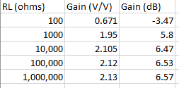
Before calculating the gain and output voltage I needed to add an RFC between RD and the drain of the JFET. With the RFC added I now now measure the gain as a function of load resistance. The table and graph is shown below with all the other pictures.


After adding the CS amp to the CE amp I built a two stage RF amplifier. The Q-point for the npn BJT was (0.34 V, 0.32 mA). To complete this section I measured the gain with various values of load resistance and filled out Table 5.4 which is shown below.
This is the last section of the lab which was to add the following RF amplifier to complete my radio. I have decided to use the CE-CC audio amp, biased diode detector circuit, and the two stage RF amplifier to build my radio. I did not obtain an output signal from the oscilloscope due to wiring failure.

Pictures
RF Amplifier

Two stage amp
RL= 1M ohms

Two stage amp
RL= 100k ohms

Two stage amp
RL= 10k ohms

Two stage amp
RL= 1k ohms

Two stage amp
RL= 100 ohms

Radio in LTspice
the radio I designed on LTspice because I couldn't get an output signal

Transient Simulation
output signal for my radio


Reflective Writing
RF Amplifier
This lab was somewhat successful in that I figured out what parts I was going to use to build my radio. I never got an output reading on my oscilloscope but I feel very confident that in the next week or so I will overcome these struggles and figure out the problems.